What is Voltage Drop?
Voltage Drop can be defined as the loss of voltage as electrons flow through a circuit due to the resistance (impedance) in that part of the circuit. So, in other words, it is the amount of voltage lost in the circuit due to resistance. Voltage Drop is a natural part of a circuit and will occur through the materials that are a part of it (wires and connectors) as well as the components. It is important to understand that the drop in voltage is due to resistance (intended to be there or not) and will always be present. We can use voltage drop to our advantage in testing, but also knowledge of voltage drop will assist with the pinpointing and diagnosing of faults or corrosion in electrical systems.
Why do we experience it?
Voltage Drop is either expected and accounted for in circuit design or is present at a level not expected in that circuit’s design. It is only when voltage drop is big enough that it causes a problem big enough to land it in the bay. Voltage drop can occur because a component is drawing too much load (internal fault), because a connector or wire has corrosion or unexpected resistance in it, because there was an unexpected circuit added to the power feed (think DIY installations and radio installs, light bars, train horns, etc.…) or some other factor that caused the OEM wiring diagram to change.
How do we experience it?
When Voltage drop is present on a circuit that was not intended to be there, we can often see components, or sensors operating at extremely low levels, providing random readings, completely stop all together or some combination of the aforementioned. Experiencing voltage drop in a vehicle can be tricky because components and circuits are not always live and activated and not all live and active circuits are able to be visually inspected in operation or have noticeable degradation at all times. In other words, sometimes experiencing voltage drop is not always obvious.
Also, depending on makes and models, some vehicles may activate components, motors or loads by “pulling” a circuit to ground via a relay. Whether through the relay or the ground or a combination of the module connections, the contacts in these systems can begin to go carbonize, corrode or break causing circuit operation to fail or degrade severely. One example of this was in a 2004 Corvette where the passenger door lock would not always close when the power locks activated. The lock would have no problem slamming open, but it would not always lock automatically, or it would seemingly have a hard time doing so (slower and clunkier than the crisp “unlocking”). Before we saw the vehicle, the lock actuator was already condemned, and new parts were ordered by the owner. (It came in for a removal and install).
After running through standard testing (visual inspection, loose connections, corrosion and power at all the right points) and after going through the wiring diagram it was easy to see that the Door module was meant to apply ground to the different sides of the actuator and change its polarity in order to Lock or unlock the door. Once we tested the circuits for load carrying ability and the lock actuator with jumper cables (yes fused), we set our eyes on the door module. Once removed and opened we could see the carbonized contacts at the ground points inside. Very often in these Corvettes the door control module will actually have ground contacts that start to carbonize and create high resistance (which happened to be the case here) at the contacts inside the module itself. These carbonized contacts allow for voltage and amperage to cross and operation to occur, but they began reducing the amount of current flow (creating voltage drop) and caused degradation of the operation over time. In this case, the module itself could be replaced for $40 (it happens so often on these there is a specialized market in rebuilding them) rather than a $300 actuator. The point is that the amount of carbon scoring and buildup on the contacts was still allowing operation of the circuit but at a very low level because of the voltage drop occurring at the relay.
How to find it
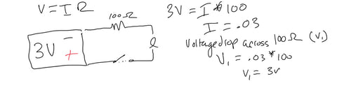
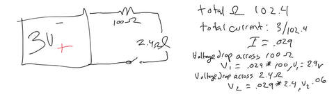
Although in the case of the corvette we were able to visually see what was causing the voltage drop (and bad ground) for the door actuator we could have gone the extra step and activated the module relay and closed the contact and then done a voltage drop test to confirm the diagnosis. When doing a voltage drop test, we must first identify the whole circuit and all components on it. Then we must confirm the source voltage for that circuit and then begin to rule out the power fees and ground feed. We must test (while the circuit is powered up) the voltages present on the power and ground feeds (from the power feed to the component then the component to the ground feed). We should typically never see more than 100mV to 200 mV on a circuit ground feed or power feed also all voltage should be “dropped” or consumed across the load and almost none should be lost in the wires, connectors or switches.
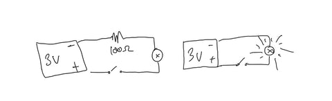
The below video will go through this process showing voltage drop testing on a good circuit and then testing a circuit with a bad ground.
In the case of the video we have small bulb so the amperage will be low (allowing us to test the amperage of the circuit inline or in series, but if dealing with higher amperage components we can use an amp clamp to find the amperage and see the effects of voltage drop) but in a standard voltage drop test... you only need a voltmeter.
The following is the process we use when doing voltage drop testing:
- Confirm your Power Source voltage (battery or power/ground feed for the component).
- Going from Power source positive to component positive while the circuit is in operation measure the voltage
- Going from Component Ground connection to the power source ground feed measure the voltage
- If voltages appear above 200mV then test the connection points and inspect the connections of the feed.
How to resolve voltage drop
Depending on what is causing the voltage drop, corrosion, carbonization or loose connections there are several options to resolve. Loose connections are probably the easiest to resolve, with reconnecting and ensuring a tight fit via pressure and gaskets. When it comes to corrosion on things such as battery terminals and connections, cleaning (sanding and reconnecting and applying a dielectric grease) and protecting the terminals can keep your electrical gremlins away. Carbonization of connections and relays is a little more permanent because the copper or brass inside these connections will actually burn as higher currents pass through them and create a carbon barrier where the material is unable to flow electrons, so replacement will more than likely be necessary. Corrosion in wires and connectors may be solvable with cleaning and protection, but if not, proper replacement is important to allow for the amperage flow to continue, but also proper sealing and reinstallation so that we do not open areas for more corrosion down the line (pun intended). Once the high resistance cause of voltage drop has been identified in the circuit, its removal or replacement is necessary for normal operation to occur.
Learn more about our Voltage, Amperage and Resistance and testing for them here:
https://shop.curienllc.com/blogs/resources/what-is-voltage
https://shop.curienllc.com/blogs/resources/what-is-amperage
https://shop.curienllc.com/blogs/resources/what-is-resistance-and-how-to-measure-it