What is Resistance?
Resistance is defined as the impeding, slowing, or stopping effect exerted by one material thing on another. Before we talk about electrical resistance it is important to understand that on a vehicle that there are 2 types of resistance you will run into (Pun intended). The first type of resistance we are all accustomed to hearing in testing is Electrical resistance and the second type is mechanical resistance. We must use our senses and measurements to understand what types of resistance we are encountering when diagnosing issues with a vehicle or circuit, but we can also make determinations about what is going on based on how the circuit is operating. As in last week’s article on Amperage, Amperage is the electron flow (current flow) through a circuit that is the actual work force of a battery (or power source) when we are powering a circuit. When power a circuit that has resistance, Amperage on that circuit can either go up or it can go down. Electrical resistance causes amperage in a circuit to go down (it is converting amperage into heat loss). Mechanical resistance will cause amperage in a circuit to go up because it causes a need for more work force (amperage). By measuring the parameters of a circuit (voltage and/or amperage) we can start to identify the type of resistance we may have on a circuit.
Mechanical Resistance
Mechanical resistance is the presence of extra load on a circuit that may not normally be there or may just temporarily be there. Mechanical resistance is best seen in motors and is the reason we see inrush current for all components. Inrush current (more details in the last article here) is the extra amount of effort of the work force electron flow (amperage) that it takes to get something started. In the case of a motor, inrush current may be the extra amperage it takes for the electrons to actually push the motor from a dead standstill to moving. Once the motor gets moving, the necessary amperage to keep it operating actually reduces (much like pushing a chair across a room, the first “Umph” of effort gets it moving, then sliding it is easier) once it’s going. See this video how how inrush current from the fan motor can be seen both numerically and in graphing.
If mechanical resistance occurs or keeps past the intended inrush time or sporadically during operation it can increase the amperage draw of a circuit causing fuses to blow or draw to exceed parameters for other components on the circuit. Here is a circuit setup to show you mechanical resistance in action:
As seen in the below video, as we add mechanical resistance (something blocking the fan) to the fan being powered the amperage draw of the motor increases as it requires more energy to operate at the speed it was designed to operate at.
Electrical Resistance
Electrical resistance is the opposition or “road block” to the current flow (of electrons) in a circuit. Resistance is measured in Ohms and is recognized by the Greek letter omega (Ω). Knowing about resistance in a vehicles circuit is important because it is either meant to be there…. Or it is not. Honestly all materials will naturally resist current flow (electron flow) to some degree but depending on how they are meant to will either have them be considered Conductors or Insulators. A Conductor is a material that has very little resistance and will allow current to flow easily through the wire. An insulator is a material that has a high restriction on the flow of Amperage. Think of a wire wrapped in rubber, the wire is a conductor and the rubber shell are an insulator. The easiest way to imaging resistance is as a workforce stopper.
You can imagine that resistance is the plaque buildup in the picture of this artery, the amperage is the blood flow and the voltage is the potential of flow itself:

Resistance that is meant to be in a circuit is often to provide feedback for a variable that is being measured such as a thermistor taking temperature measurements and variably changing resistance to feed that information to a computer, or a fuel level gauge sender that is telling the computer how much fuel is in the tank by providing variable resistance based on the location of the plunger as an example. Resistance is important to know and measure so that we can accurately determine the operating health of a circuit.
As before mentioned resistance is either meant to be on a circuit or it is not. For circuits that are not meant to have resistance (or have very little), the presence of resistance can really muck up the operation of the circuit, whether it is on the ground, on the power feed or in the component itself. As shown in the image below a 100 Ohm resistor on the ground (Bad Ground) halts the operation of the fan.
Resistance on the ground feed (ground) of the circuit can cause the component to operate at much lower levels than anticipated or completely stop working because the circuit is unable to be completed or might have much more voltage draw on it than it was built for. Resistance on a power feed can similarly cause much more amperage to be consumed in the circuit and will ultimately diminish the capability of the circuit to operate or cause it to stop operating all together. When there is resistance on a circuit like we are describing it will always create voltage drop on that circuit. Simply put voltage drop in a circuit is the unintended use of voltage for a specific circuit that causes that circuit to exceed its normal operating parameters and makes it not work right lol. Typically, resistance in a circuit such as that caused by a bad ground will create an excess of heat in that particular area where the resistance is occurring and depending on how much amperage is trying to go through that circuit it can create some major red flags.
Low Resistance
battery Cables, copper cables and the wires and materials meant to feed power and grounds to a component or circuit will typically have no to extremely low resistance. This is because they are intended to flow as much current through them as possible without inhibiting that flow (impeding or resisting). Low resistance however is not a “tell all” for whether or not a circuit can flow current, but it is a major influencer in a circuits ability to operate correctly.
High Resistance
Having a high resistance or high impedance will stop the flow of current. A voltmeter such as on the N2 has a high impedance on it (>10M Ω - Greater than 10 Million Ohms) so that it will not allow amperage (current) to flow through it (it stops it from becoming a jumper wire) while measuring voltage. High resistance on a circuit that is meant to be there is either being used to tell a computer or other sensing circuit some factor about the environment around the vehicle or is being used to stop the flow of current in the vehicle/circuit.
How to measure resistance
I am going to show you 2 ways to measure a resistance or Ohm readings. The first is by being in series (in line with a circuit) and measuring the Ohms of that circuit with a Meter such as that on board the N2 and by calculating resistance via ohms law. We are going to show you both methods below.
Inline Resistance Measurements
Measuring resistance inline is the most accurate way to measure resistance of a component or circuit. In this image as the N2 is a part of the circuit and no power is connected we can be confident in our ohm reading. Please note that Resistance Measurements cannot be taken with voltage on the line otherwise they will give inaccurate readings. The Meter is testing resistance by outputting its own voltage and amperage from one probe tip and watching the return flow on the other end. In this type of testing we want to be sure to take the inherent resistance of our own test leads out of the way by zeroing the N2.
Calculation Measurements
In our other articles (and this one) we mention Ohms Law Calculations (Go back and read them here). In the use of Ohm’s law, we find that Voltage is equals to current multiplied by resistance. In the simplest terms, Ohm’s law tells us that Voltage, Amperage and Resistance all have a relation to each other and that a change in that a chance in 1 will have an effect on the other 2. In the equation V=IR (Volts = Current * Resistance or Ohms Law) we can find any value we want V (Volts), I (for current) or R (resistance) if we have the other 2.
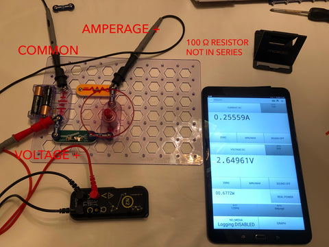
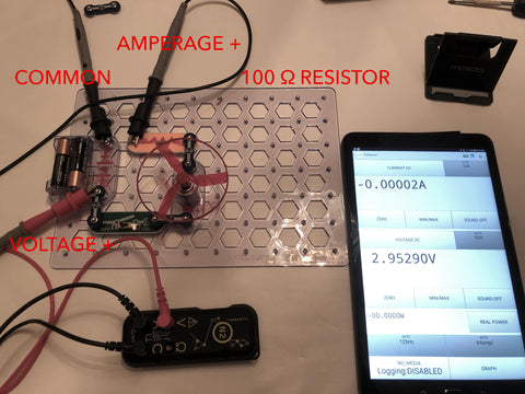
In the case of this test circuit, if we have our amperage and Voltage we can begin to calculate Ohm’s law and find the calculated resistance of the circuit or component we are operating on as shown below. In the below video we can see that in this circuit we have a Voltage of 2.95290 and an Amperage of .028416. Based on Ohms Law if Volts = Current * Amperage then we should have a formula such as
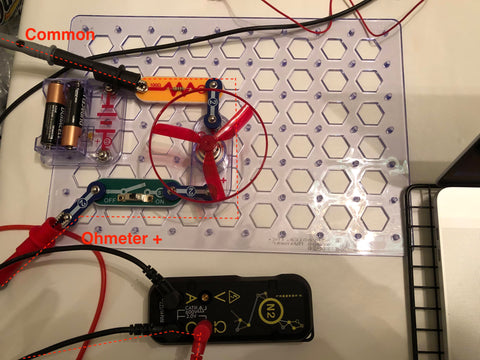
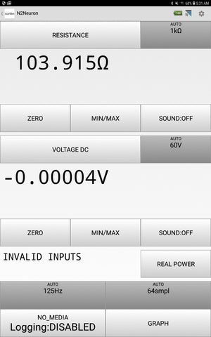
2.95290 = .02835*R. In order to determine R or resistance we need to divide voltage by amperage (2.95290/.028416=R) to find that R = 103.9168. Now that is pretty close to the 100 Ohm resistor on the circuit, but we must not forget the entire circuits resistance. When we remove the power source from the circuit and do an in line ohms test as in this image:
We find an ohm reading of 103.915 Ohms (as seen below).
Calculated Resistance can be helpful in determining the health of a circuit if you are unable to visually find any issues with the circuit or components.
Voltage Drop & Ohms Law again
I am brining up voltage drop again because it is most often the culprit of circuits that we find that are inoperable that still have power on them. The number 1 reason we have voltage drop is because of resistance. Voltage and Amperage are directly affected by Resistance as per Ohm’s law and as you just saw in the videos and images prior to this. In our next series of writings, we are going to to dive into what voltage drop is, how to find it, what it means and how to use Ohm’s law to find out if we might be operating out of Spec, going bad or be in good shape.