What is Amperage?
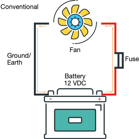
Amperage is the current flow of electrons from the negative side of the battery to the positive. In our simple fan circuit example below Amperage is the orange arrows of electron flow going through the wires. In this image labeled as Electron Flow, we are showing the literal path that Electrons are taking in a standard circuit from a Low pressure (ground/Earth) to the High Pressure (Live/Hot). Although this is more scientifically accurate, in Automotive we relate to and more often use the conventional current design in circuits and distinctions.

Conventional Current assumes that current flows out of the positive terminal (High Pressure), through the circuit and into the negative terminal (Low Pressure) of the battery. Because this is often what is used in automotive we will use this going forward because symbols such as diodes and transistors as well as rules such as “Right-hand rules” were created using conventional current.
Simple DC Amperage
Because we are dealing with Automotive we are discussing the Amperage of DC Circuits (Current only flows in one direction). Amperage Flow or Current Flow is the amount of electric power flowing through the circuit (system) that creates an electromagnetic force (emf) but we can understand it as the work force of electricity. The Amperage is what is flowing through this motor and pushing the fan on its way from the positive side to the negative side of the circuit. Although the Amp or Ampere is measured as the flow of electrons over a point over a specific set of time, we will be focusing more on its practical application to testing and automotive.
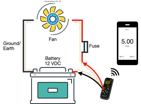
Because the amps are the workforce of the battery flowing through the vehicles circuits and thusly “activating” the things that need to be working (electrically) it is important to always have the correct amount of electron flow to components. Whether starting a motor, fan, relay or lightbulb everything on the vehicle has a specific amperage draw. In the image below we can see that the Operating specification of the fan is 12 Volts, 5A meaning that the Fan is designed to operate on a 12V circuit and run at 5 Amps of current.
Inrush Current
Unless you are Captain Kirk at the helm of the starship enterprise shouting down to Scotty for more power, most components will only draw the current that they need to operate at the level they are rated for, however that does not include a brief moment for something called inrush current. Inrush current is the input surge of current, also known as the “switch-on surge” of current that is the maximum instantaneous amperage drawn by a component when first turned on. In the image above we can see that the although the fan is rated for 5A or 5 Amps of steady state current draw, it has an inrush of 9 Amps (bottom right hand corner of the phone screen). This inrush is the additional workforce that was needed to get the motor moving from a complete stop to its standard operating amperage. You can think of this as if you are trying to push a large cart across the shop floor, initially you have to give it just a little extra help to get it moving, but once it is moving, momentum and the wheels really help to keep it going.
Why do we need to measure Amperage
Understanding the current draw of a circuit or component is crucial in automotive as it can help you identify if the amperage draw of a component or circuit falls below, at or above the parameters set by the manufacturer. Essentially we can make determinations about the health of a circuit or component based on its’ amperage draw. If the amperage draw is too low, it may indicate that there is a problem with the power source and that the component is not at full voltage, current carrying capacity, or that the power feeds connected to the component are not in spec, or that there is resistance on the circuit or a loose connection somewhere. A high amperage draw may indicate that the component is starting to go bad or that there is something blocking the normal operation of the component (such as debris in a fan or motor), or that there is resistance somewhere in the power feed. Also if there is amperage on a circuit when there should be none, it can indicate a number of other electrical gremlins including a parasitic draw or short somewhere in the system.
How to measure amperage
There are a few ways to measure amperage in a circuit. Firstly a measurement device like the N2 Neuron is required because we are measuring the amount of electrons flowing past 1 point in 1 second…6.24 billion billion (6.24 x 10¹⁸) electrons in 1 second = 1 Amp. Once we have the ability to measure amps, there are 3 methods to find the value of amps in a circuit or component.
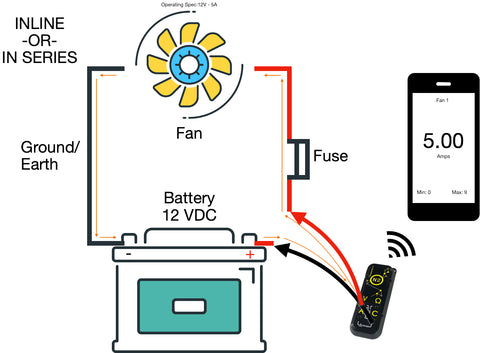
Inline- Inline or in series testing of amperage is completed by putting the measurement device in-line or in series with the circuit (making it part of the circuit) and measuring the amps as they flow through the device and through the circuit. Inline testing although accurate is the most limited option as in automotive we typically want to measure a circuit without modifying its original operating environment, disturbing any communication or connections to pcm/ecms in the process of testing and we do not have the ability to test (typically) more than 10 amps at once. Most meters and testing devices are rated for no more than 10 amps.
 Inductive (Hall effect)- inductive testing or testing with an amp clamp specified for DC Circuits (Hall effect is typically used) is one of the more common ways to test for amperage that allows for the circuit to stay intact and simultaneously provide feedback about the electrons moving through the circuit. The way that the inductive Hall effect clamps work is by measuring the changes in magnetic field of the ferrous material core of the clamp. In other words, as the electrons in the wire are flowing, they create a magnetic field. Because we know the clamp has a known magnetic field and are able to measure it, when the clamp is placed around the wire and the electrons flowing through it change the magnetic field of the clamp we can measure the differences and come out with an amperage reading. Although this is a simplified explanation most clamps will output a millivolt reading and have that associated to an amperage reading, 1mv = 1 amp for example. Also amperage clamps typically come in multiple ranges (low and high amp clamps) because when measuring small amperages you will need a sensor that can handle the low ranges in magnetic field change versus when reading a high amperage you will need a sensor that can handle the higher ranges in change in magnetic fields.

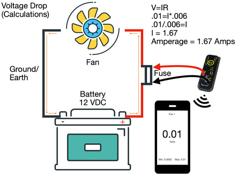
Calculations (V=IR) - Another way to measure amperage is via calculation. In the use of Ohm’s law we find that Voltage is equals to current multiplied by resistance. In the simplest terms, Ohm’s law tells us that Voltage, Amperage and Resistance all have a relation to each other and that a change in 1 will have an effect on the other 2. In the equation V=IR (Volts = Current * Resistance or Ohms Law) we can find any value we want V (Volts), I (for current) or R (resistance) if we have the other 2…. This is now taking us back to high school math, and darn it if we didn’t listen then lol. Because we know Ohms law we can calculate the amperage value of a circuit if we know the voltage and resistance of that circuit through voltage drop. This allows us to use a shunt of a known resistance value in-line with a circuit, take a measurement of the voltage drop across the shunt and then calculate for amps. In automotive we can do this with fuses in a vehicle to determine the amperage on that circuit. This is extremely helpful for finding parasitic draw without pulling fuses or disrupting the circuits natural state. In the image below we are showing how to calculate the amperage draw of a circuit by measuring voltage drop across a fuse. In this scenario we can imagine that the is some component drawing the amperage that shouldn’t be and the vehicle is in a key off position. With that assumption in mind, we can measure the voltage drop at .01 volts or 10 MilliVolts, knowing that the resistance rating of a JCase 20 Amp Blue Fuse is approximately .006 Ω (Ohms) we can draw our calculation as .01 = I * .006 . In order to find I (or Amps) we need to “even out the equation” by dividing the left side by the number we know on the right (.01/.006 = I). When we calculate .01/.006 we find that I = 1.67 so with the simple calculation using ohms law, and calculating for I or current, we find that this circuit which is supposed to have no draw (or virtually no draw) has a 1.67 A draw which will more than likely drain a battery and be considered a parasitic draw (More on that in future articles).
Do I need to know more than amperage?
When it comes to testing the electrical issues on a vehicle it is important to know as much about a circuit and its operating health or state so you can make the best determination about what is going on. As described in the last paragraph regarding ohms law calculations, with a little bit of information and some basic math we can find out more about what is going on in a circuit that our own tools (today) can tell us. Knowing amperage in conjunction with Voltage allows us to calculate for resistance, knowing voltage and resistance allows us to calculate for amperage. Being able to manipulate the data in our hands leads us to data intelligence. As we dig deeper into the world of automotive application testing it will become more apparent that we are living in a world of information, and we just need a little help to extract what we need to get to where we want to go.
Please see the prior article in our series: